Introduction
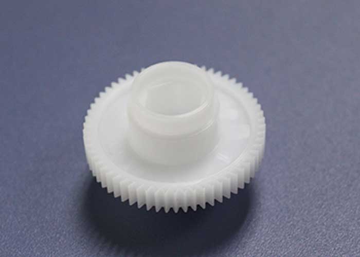
Plastic gear mold design is a highly specialized field that integrates principles of mechanical design, material science, and injection molding. Due to the complex geometry of gears and the unique shrinkage behavior of plastics, gear mold design requires advanced methodologies to ensure dimensional precision and functional performance. This article explores the essential aspects of designing and manufacturing plastic gear molds, from theoretical cavity design to gate and venting strategies, and finishing with mold fabrication techniques.
1. Cavity Design: Beyond Linear Shrinkage
In plastic injection molding, gear profiles undergo non-uniform shrinkage due to asymmetrical cooling and fiber orientation. Conventional isotropic shrinkage assumptions fall short when applied to involute gear profiles.
To resolve this, designers adopt the variable module method, adjusting the gear module in proportion to the material’s shrinkage rate. This method considers the pitch circle diameter variation during molding and helps achieve high-precision gear teeth after cooling.
2. Gate Design: Achieving Dimensional Stability
Gate placement dramatically affects the radial runout and overall mechanical integrity of plastic gears.
A three-point balanced gating system is often preferred, as it promotes even material flow and minimizes weld line defects. Compared to a single-point gate, this layout reduces fiber orientation inconsistencies and shrinkage anomalies, resulting in superior gear precision.
3. Venting: Critical for Incomplete Fill Prevention
Proper venting on the tooth surface is crucial for removing trapped air during injection. While polished surfaces enhance gear performance, they also hinder air escape.
To mitigate this, shallow venting grooves are machined directly into gear cavities—especially at the end-of-fill regions—to ensure complete material flow and reduce the risk of short shots.
4. Mold Structure: The Role of Multi-Plate Design
Due to the centralized point gates used in gear molding, three-plate mold structures are common. These structures allow for clean gate separation, sequential parting, and controlled ejection, ensuring that the molded gears retain their intended shape and detail without deformation or breakage.
5. Precision Manufacturing: From Wire Cutting to EDM
Plastic gear molds are typically constructed from two main components:
- Gear cavities, which demand high precision and are often produced using wire EDM, conventional EDM, or electroforming.
- Mold frames, which provide structural support and follow standard injection mold fabrication techniques.
The choice of gear cavity machining method depends on gear type (straight or helical) and required tolerance levels. For complex geometries, EDM remains the go-to method for achieving superior accuracy.
Conclusion
Designing plastic gear molds involves more than duplicating gear profiles—it requires a deep understanding of shrinkage behavior, material flow, and mold kinematics. Techniques like the variable module method and multi-point gate layouts are crucial to ensuring product consistency and performance. As gear applications continue to grow in robotics, automotive, and consumer electronics, mastering mold design for plastic gears becomes ever more critical.
